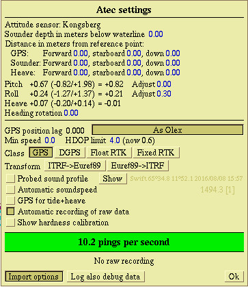
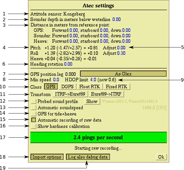
Atec system The page is updated regularly: Last updated: 2022-02-24
Section - "Atec system"
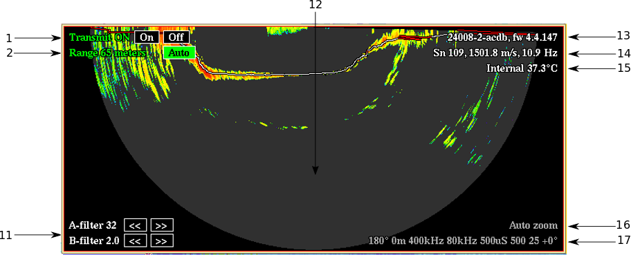
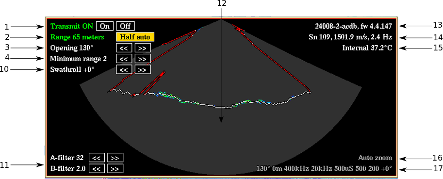
Description

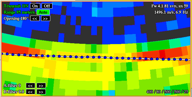
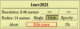
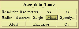
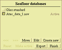
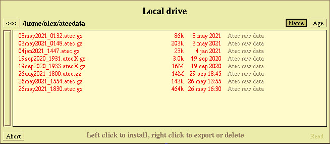
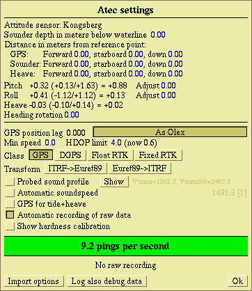
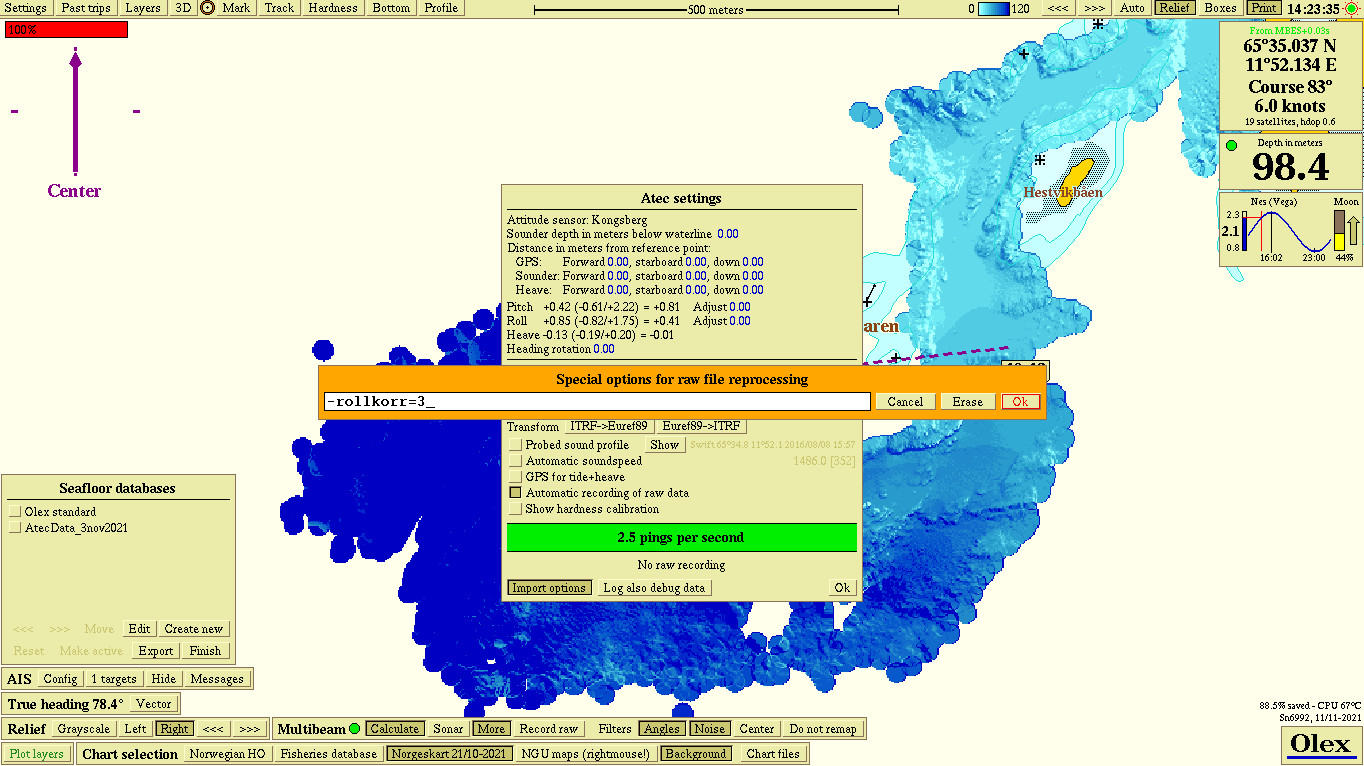
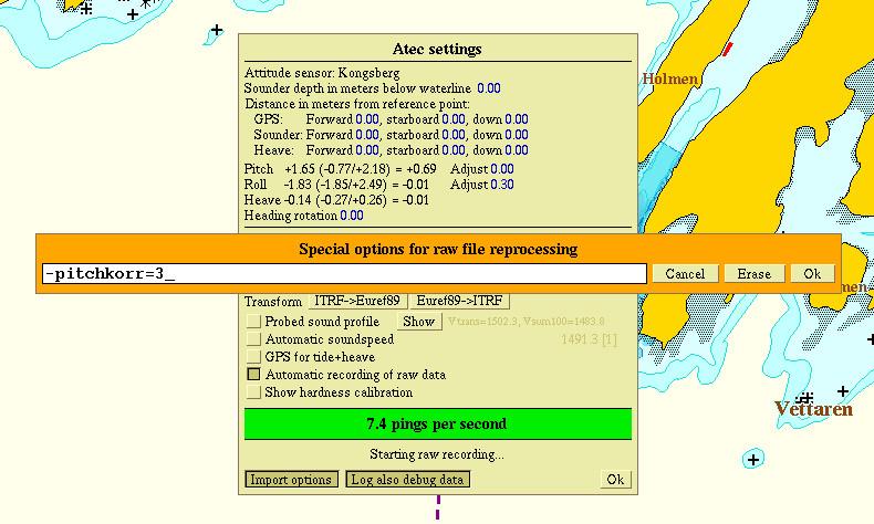
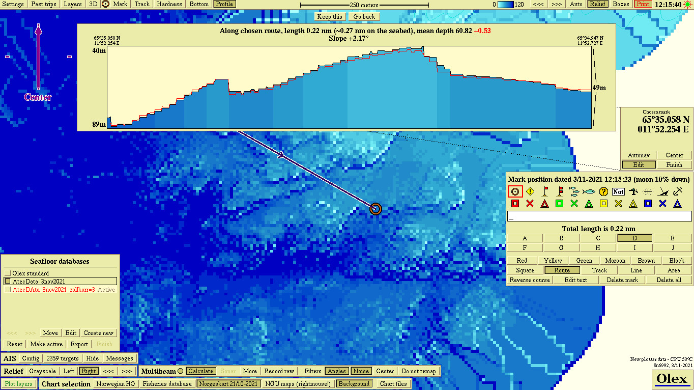
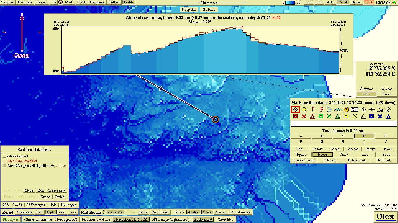
The Atec multibeam sonar is designed for high resolution seafloor survey. This compact sonar, with integrated transceiver and sound speed sensor, connects directly to Olex via Ethernet and is automatically controlled without any need for manual operation. The sonar uses broadband technology for increased range and accuracy, and has a high ping rate, wide maximum swath coverage of 180 degrees and 0,5 – 500 meters depth range. The Atec software module in Olex becomes the sonars top-end software, and various parameters like pulse length, bandwidth etc, is changed automatically. The sonar is continuously adjusted to provide maximum ping rate and best resolution according to the varying water depth. Atec can also be controlled manually to obtain more fine tuning. Via our dealers, we can offer a complete survey system consisting of Olex, Atec sonar and different solutions for position, attitude, and sound velocity. The seabed data can be exported as a complete Olex 3D model, as text files for import to other GIS, or as screenshots.

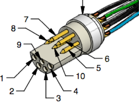
A typical delivery of Atec can comprise:

  • Olex software, full
  • HT and Atec software nokkel
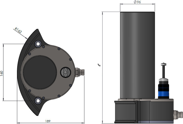
  • Atec 200 sonar
  • Spatial or Certus motion sensor or roll-, pitch- and heave- sensor and heading source.
  • (RTK -) GPS
  • External sound speed sensor

Diagram

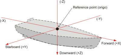
Depending on area of use and accuracy requirements, a complete Atec system comprises Olex, Atec sonar and different solutions for position, altitude, attitude and sound speed.
Two different diagrams are provided. Interface capabilities, power supplies and power cables are not shown.

Atec with AHRS - Attitude and Heading Reference system.


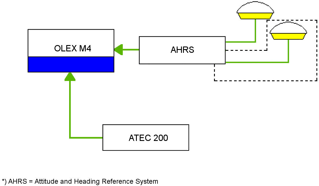
AHRS is a common name for attitude reference-systems consisting of sensors on three axes that provide attitude- and heading- information. AHRS-systems makes a more cost effective solution than conventional high-grade instruments.

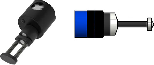
Spatial - Advanced Navigation

Spatial is a small position and attitude sensor from Advanced Navigation in Australia. It combines accelerometers with GPS and magnetic compass, and provides pitch, roll, heave, heading, position, course and speed. A complete Atec system may consist of Olex with ATEC and HT software, Atec multibeam sonar, and just Spatial. Spatial promises 0.1 degrees accuracy in pitch and roll, 0.8 degrees in heading, and 5 cm or 5% in heave. The accuracy depends on the placement and calibration of the sensor and the magnetic compass. The sensor should be mounted close to vessel CG and its antenna must have a clear sky view. A practical site may be low in the wheelhouse, with the antenna outside.

Certus - Advanced Navigation

Certus Evo is an ultra high accuracy GNSS/INS that provides accurate position, velocity, acceleration and orientation under the most demanding conditions. It combines ultra high accuracy temperature calibrated MEMS accelerometers, gyroscopes, magnetometers and a pressure sensor with a dual antenna RTK GNSS receiver. The Certus EVO is a more accurate alternative to Spatial, and uses RTK-GPS combined with 1 or 2 external GPS-antennas for better positioning.

Atec with external sensors
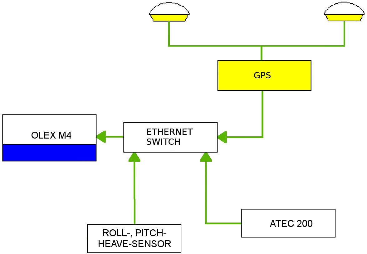


GPS - and RTK-GPS

Ordinary GPS-receivers has a normal accuracy of app. metres if the sky view to the satellites is good. RTK-GPS makes a considerable improvement in positioning, and is the application used to correct for common errors and delays in the current satellite navigation. The phase difference in the signal carrier is measured, and time corrections from reference stations on land are received. The RTK-service is provided from "Det Norske Kartverket" in Norway, or e.g., NTRIP in other areas.
See RTK - Real Time Kinematics for more information.

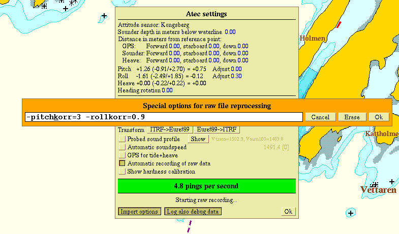
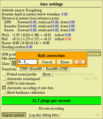
MRU - Motion Reference Unit

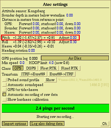
The Kongsberg MRU is one of the best motion sensors on the market. It is suitable for any marine operation that requires attitude determination and motion compensation. The sensor has low angular noise and high stability and provides high accuracy motion measurements in all dynamic environments. E.g the 5th generation MRU has a documented roll- and pitch accuracy of 0,01 deg, and angular noise less than 0,02 deg. The MRU can be mounted inside the ship hull, close to the barycentre. Waterproof versions can be mounted directly on the hull.

Heading source

Different heading sensors can be used with Atec 200, e.g., satelit compass from Furuno, JRC or TSS DMS 05.

Network

The Atec 200 uses Ethernet communication, and when using external GPS and sources for altitude and heading, an external ethernet- switch is required.

Installation

A simple answer to "where to install the sonar head" is difficult to give. The physical location of the sonar head depends on the construction of the vessel and design of the hull, and how the water runs along the hull. However - there are some guidelines to make the installation easier:

  • Deep mounting to avoid the boundary water layer.
  • Keep distanse from propellers.
  • Keep distanse from thrusters.

Deep mounting

The upper water layer contains a large amount of small air bubbles created by breaking waves. In heavy waves appr. 5-10 metres of the upper layer may be filled with air-bubbles, which reflect and absorb the sound waves. This creates distortion and might completely block the signal transmission. When the vessel moves through the water, the friction between the hull and the water creates a boundary layer. The thickness depends on the speed and design of the hull. Any objects protruding from the hull disturbs the water flow and increases the thickness of the boundary layer. The water flow in the boundary layer might be turbulent or laminar. A laminar flow is calm, and the water flow is nicely ordered. A turbulent flow has a stochastic and chaotic pattern, full of swirls and eddies. The boundary layer increases when the flow changes from laminar to turbulent.

Distanse from the propellers

The propellers are the dominant source of noise on most vessels. The motion of the propeller blades creates air bubbles, and noise is transmitted through the sea water. In worst case this might reduce the maximum range capability of the of the sonar. The sonar head should be placed far away from the propellers, perhaps in the middle or fore part of the hull. Out of direct sight from the propeller is preferable, propeller cavities might be strong and cause poor signal transmission.

Distance from bow thrusters

Bow thruster propellers are one of the worst sources to noise. When in operation, the bubbles and noise created by the thruster makes the sonar useless no matter where the sonar head is located. The thruster chambers create turbulence and might release air bubbles a long time after use. The sonar head must be placed away from the thrusters, in most cases a location forward of the thruster is the best solution.

Protruding objects

Objects like anodes, transducers and other equipment protruding from the hull might cause turbulence and flow noise. Do not place the sonar close to any of this object, as this might cause reflection and signal distortion.

Installing the sonar head

The Atec 200 sonar is normally used for seabed mapping. The sonar head should be mounted on the hull, parallel to the keel. Transducer elements pointing downwards. If the vessel has a deep keel, the transducer must be mounted on the lower part of the hull to avoid reflections. The accuracy of the system depends to a large extent on the placement. Although most parameters can be corrected in software, it is an advantage to have the most accurate installation possible.

Note

The risk of galvanic corrosion must be considered in the design of the mounting structure. All metal brackets and fastening bolts must be isolated from the sonar housing. Be sure to use the original fastening bolts and the nylon counterparts when installing the sonar head. Periodic inspection of the mounting bolts will be required in a permanent installation.

Mounting

Mounting arrangments for both permanent and temporary installations are possible.
Temporary installation may include:

  • On the side or in the bow of vessels.
  • On ROVs or other subsea equipment.

Permanent mounting

There are several solutions for installation of the Atec 200. The sonar can be mounted outside the hull, on a mounting bracket to avoid the deadrise angle of the hull. This bracket can be made at a shipyard, or custom made brackets may be ordered via Olex AS. On vessels travelling at high speed a blister mount might be the best solution. This method also protects the Atec 200 from objects in the water hitting the sonar head.

Temporary mounting

The small size and weight of the Atec 200 makes it portable and easy to move between several vessels. For temporary installations the sonar might be deployed on a pole etc. fixed to the side or in the bow of the vessel. The main consideration is that the system must be rigid, and that the sonar is deeply submerged in water.

Click to see examples of Atec 200 mounting.

Cables and connections

Power supply

Atec 200 works on operating voltages between 20   29 VDC. The power source must give a constant output voltage over time, so the sonar is not in risk of being damaged due to rise in current caused by unintentional voltage drops. (I.e., if a battery is used as a power supply.)

Cable

The Atec 20 comes with an 8 meters cable, if a longer cable is required a 20-meter-long version can be supplied on request. The cable contains a serial cable, an ethernet cable and voltage conductors, all encapsulated in one single saltwater resistant outer mantel. The cable can be fully terminated on delivery, or the connectors can be mounted later if the cable is to be pulled through narrow pipes or spaces. The sonar has one single connector on top of the sonar housing which is common for power, ethernet and serial signals. Before the cable is connected to the top socket, be sure to check the O-ring/gasket inside the connector housing. Any cracks or damages to the gasket may cause leakage and in worst case make the sonar fail due to water intrusion.


Cable layout

Power cable

The 2 voltage conductors, red and black, connects to positive and negative pole on the voltage source respectively.

Serial cable

The serial cable is mostly used for configuration and troubleshooting, not during survey.

Eternet cable

All data and communication with Atec 200 is sendt via ethernet. Just connect the RJ-45 plug to Olex and the communication is created.


Lemo pin Cable Signal name RJ45 (Pos 200) D-sub (Pos 201) Black 4mm (Pos 202) Red 4mm (Pos 203)
1 black
(red pair)
LAN TX + 1
2 red LAN TX - 2
3 black
(blue pair)
LAN RX + 3
4 blue LAN RX - 6
5 black
(green pair)
Rs232 Tx 2
6 green RS232 Rx 3
7 black
(white pair)
GPIO N/C
8 white RS232/GPIO
GND
5
9 black
0.5 ㎟
Power GND Connected
10 white
0.5 ㎟
Power 24 VDC Connected

Cable maintenance

Unplug and clean all connectors periodically. Use canned compress air, or an air compressor if available, to clean dust from connectors and capsules. Look for wear and tear on cables, and make sure there are no breakage or pinches on the cable. Cables submerged in salt water should also be inspected from time to time. Look for cracked or porous insulation, and look for tearing and signs of galvanic corrosion on the connectors. See Inspection for detailed information.

Technical specification Atec

This section provides the specifications for the Atec 200 multibeam echosounder.

Weight and dimentions

Weight: 6.0 kg
Length: ~ 289 mm
Height: 189 mm
Width: 244 mm
Distance c/c mounting bolts: 160 mm

Performance

Swat coverage: Up to 180°- typical 130 °
Number of beams: 256
Operation frequency: Nominal 200 kHz (100 - 800 kHz)
Bandwith: 0 - 40 kHz
Ping rate: Up to 50 Hz
Maximum detected depth: Up to 600 m - nominal 500m
Minimum detected depth: 0.5 m
Range resolution: < 10 mm @ minimum range
Resolution: 2° across and along track

Power

Voltage: 20 - 28V DC
Power consumption: Peak: 5A@28V
Nominal: 2A@28V
Standard cable length: 8 m
Maximal cable length: 50 m

Environment

Storage temperature: -20 °C - + 60°C
Operating temperature: -4 °C - + 40°C

Interface

Interface: 100 Mb/s Ethernet

Integrated sound speed sensor


Sound speed: 1400 - 1600 m/sec
Precision: +/- 0.03 m/sec
Response time: 47 µs
Pressure: Down to 6000 m
Interface: RS232 or RS485
Operating temperature: -20 °C - + 60°C
Operating voltage: (7.5 - 26V DC) uses the built-in power supply

Download PDF

Equipment handling

Transportation

The Atec multibeam sounder can be transported using all methods approved for delicate equipment (road, rail, air or sea). In general the unit must be handled with care, and packed in a transport case, carton box or similar. It must not be exposed to shocks, excessive vibration or other rough handling.

Lifting

Warning

Be careful when handling or lifting the sonar, it must not be dropped or exsposed to other rough handling. Do NOT use the buildt-in sound speed sensor for lifting!

Storage

The unit must whenever possible be stored in its original transportation box until ready for installation. Storage temperature from: -20°C - -+60°C

Storage after use

If a unit is removed from its operating location and placed into storage, it must be properly cleaned and prepared before packing. Use a mild acid or dedicated calsium remover if the sonar is covered with barnacles. Be sure NOT to use any sharp tools to remove the calsium growth!
Even very small scratches in the coating may cause galvanic corrosion. Wipe the sonar carefully with a mild detergent, and let it dry before packing. Do NOT use a high pressure hose!

Cleaning the cable

Remove the cable, and clean the rubber insulation with a damp cloth. Make sure the connector is kept dry. Do NOT immerse the cable in water after removing the connector from the sonar. .

Inspection

The sonar, connector and cable should be inspected at regular intervals.

Sonar

Check the sonar housing for sign of corrosion due to wounds or scratches in the coating and be sure the sonar is not damaged from impact with objects in the water. Check the fastening bolts and nylon plugs for possible damages.

Sound speed sensor

Check for any possible mechanical damages on the sound speed sensor. Be sure the sensor is not coated with limescale or other growth.

Cable and connector

The sonar, connector and cable should be inspected at regular intervals. Check for cracks and wounds in the insulation and be sure the cable had no deformations or twists. Check the connector for any signs of corrosion. Remove the cable plug cap from the connector and be sure there are no signs of leakage inside the connector. Check the O-ring inside the connector - if there are signs of salt deposits inside clean the connector and replace the rubber O-ring.

Operation

When Atec 200 and necessary software are installed, calculation of seafloor maps will automatically start as soon as the Olex machine is turned on. The seafloor’s ability to reflect sound, corrected for any factors that may affect the measurements, is the bases for the topography and hardness in the seafloor map visualised in Olex. The hardness is visualised using both colours and in percent, where 0% is soft or steep and 100% is maximum hard and flat. The hardness value is also visualised in the depth flag on the mouse pointer. Due to different quality requirements and calculation methods, there might be spots where there are no calculated hardness values on the map. Instead, the depth value is displayed.

System setup

Click More in the Multibeam menu to open the Atec settings panel. The values marked in blue can be changed by clicking directly on one of the numbers.


  1. Motion sensor type. If several sensors are available, Olex will prioritize the one with the highest accuracy.
  2. Sounder depth in meters below water line: this value must be entered manually after mounting.
  3. Distance in in meters from reference point (origo): Motion sensor(s), GPS and sonar should be placed near a common reference point. Theoretically near the vessels centre of gravity - with least possible vertically movement. Practically this might not be possible, and the sensors must be placed at some distance from this point. To enter corrections for this displacement   just click on the blue values, enter the correction, and click OK. The orientation of positive and negative axis are described in Coordinate System.
  4. Instantaneous values for pitch, roll and heave: Present ( min/max ) = mean value for the last 30 sec

    Example 1:


    The numbers for Pitch in this example are as follows:

    Present value: + 1.2 degrees

    Minimum registered value: - 1.47 degrees

    Maximum registered value: + 2.57 degrees

    Mean value for the last 30 seconds: + 0.81 degrees

  5. Corrections for pitch and roll can be entered by clicking on the blue numbers. Enter the correction ( in degrees) in the panel and click OK to save.
  6. The sonar may have some offset related to the centerline of the vessel. Click on the blue numbers to enter a value for correction of heading rotation.


  7. In all GPS receivers there are an inevitable time delay in the signal travelling in the antenna lead to the circuitry of the receiver. If the GPS position lag is known - enter the correction and confirm by clicking OK. Otherwise click As Olex   the software will get the correction from the GPS position lag in the Settings panel.
  8. Min speed: minimum speed required for surveying
  9. HDOP limit: The Horizontal dilution of precision (HDOP) describes the current strength of the satellite configuration (geometry), and the uncertainty of the data that the GPS receiver can collect at that moment. If this value is too high   the calculation will stop, and no depth values will be saved. Click on the number to change the value. There are tables which explains the values more in-depth.
  10. Class: different classes of GPS receivers have different accuracy.

    GPS   uses satellites to calculate the position   accuracy up to 50 meters. If GPS is selected, all depth measurements will be registered regardless of quality.

    DGPS   A Differential Global Positioning System (DGPS) is an enhancement to the Global Positioning System (GPS) which provides improved location accuracy, in the range of operations of each system, from the 15 50 metres nominal GPS accuracy to about 1 3 centimetres in case of the best implementations.

    Float RTK (Real time kinematics) - accuracy up to +/- 0,2   1 meter

    Fixed RTK (Real time kinematics) - accuracy up to +/- 1   5 cm

    If Fixed RTK is selected, depth values will be registered only of the accuracy is good enough.
  11. Transform: Click to transform coordinate references between the European Terrestrial Reference System - Euref89 (the official reference frame system in Norway) and the global International Terrestrial Reference Frame - ITRF.
  12. Probed sound profile: to get the most accurate sound speed measurement, an external probe can be used to measure and create a sound profile in the survey area. This information is then stored in a file and imported to Olex. Click Show to view more details.
  13. Automatic sound speed: uses the integrated AML sound probe on ATEC for continuously updated sound speed.
  14. GPS for tide+heave uses the GPS as source for tide and heave.
  15. See Automatic logging of raw data.
  16. Show hardness calibration
  17. View the number of pings (signals) transmittet from the sonar.
  18. See Import options
  19. See Log also debug data

Main operation

Multibeam menu

All Olex systems with Atec has a multibeam menu line in lower left corner of the screen. This line shows the sonar status and has several buttons from where the sonar can be controlled.

The coloured indicator to the left in the multibeam menu indicates status for the survey.

Survey is running as normal.
No connection.
Survey is stopped, and no depths are registered.


Calculate   turns on or off the multibeam calculation. The button flashes in black if the calculation is turned off when Atec 200 is connected. Depths will still be registered, but these vales will not be stored and used as basis for the seafloor map in the actual area.

Sonar   opens the Sonar window where full echogram for depth, opening angle and seafloor detection is displayed.

More   opens the Atec panel where settings and parameters can be changed.

Record raw   starts and stops logging of primary data collected directly from the sonar. Raw data from the sonar have not been subjected to processing or any analysis and are stored in a separate data file.

Sonar window

Open the graphic sonar window by clicking the tab named Sonar in the multibeam menu.


Zoom in or out using the left or right mouse button, respectively.

Bottom detection

When an acoustic signal (ping) from the echo sounder reaches the seafloor, the signal is reflected and returns to the sonar as an echo. The signal strength, deviation angle and signal speed of the received echo compared to the emitted signal, gives information about seafloor sediment type, hardness, and depth. The horizontal line in the Sonar window indicates the detected seafloor. All points, on which the bottom echo is based, will be visible when using the zoom function.


Colours

The colour of the detected bottom varies according to the strength of the received echo. Move the mouse cursor to one of the detected points to see signal strength, angle of the received echo and depth.


Auto - Half auto - Manual

When the sonar uses "Auto-mode" both parameters and the sonars opening angle are automatically adjusted according to the depth.
"Half-auto" provides access to change some parameters manual, while other processes are run automatically. "Manual" gives the operator access to adjust all parameters independently using the arrows.
Click "Auto" to switch between all modes.

Auto


Half auto


Manual


# Reference Description
1 Transmit ON/OFF Turns on or off the transmitting elements inside the sonar.
Green text - the survey is running as normal.
Yellow text - survey is temporarily stopped.
Red text - survey is stopped, and no depths are registered.
2 Range Manual depth adjustment (unit in metres). Use the arrows - left or right - to adjust the range in the visible depth area of the sonar window.
3 Opening Use the arrows - left or right - to adjust the opening angle. The number of beams is constant, and by adjusting the opening angle the internal angle of emitted beams are changed accordingly.
4 Minimum range Minimum range (in metres) for the sonar to register and store depth data.
5 Frequency Use the arrows - left or right - to adjust the frequency of the emitted signal.
6 Bandwidth Use the arrows - left or right - to adjust the bandwith of center frequency.
7 Pulse Use the arrows - left or right - to adjust the pulse length (in uS) of the emitted signal.
8 Resolution The seabed is simulated with coloured boxes within the beam sector. This function changes the number of boxes drawn from the signal source and down to the detection of the bottom echo.
9 Vertlen Internal description   tells something about the width of the beam angle where the detection functions searches to possibly detect the seafloor.
10 Swatroll When the sonar is mounted flat on the hull, the angular displacement of the transmitted centre frequency will be 0 and the centre beam will be pointing straight down at the sea floor. Use the arrow keys to adjust the angle of the centre frequency beam. If the sonar is mounted a bit skewed, this function can be used for correction.
11 A- and B- filter Changes the quality of the sonar image, use the arrow keys to change the emphasis on different colors in the image
12 Bottom detection Displays the seafloor as a horizontal coloured line in the beam sector.
13 Software version Software version of the sonars internal software.
14 Information Displays Atec serial number, sound speed and frequency.
15 Temperature Internal operating temperature.
16 Autozoom When the sonar runs in"auto-mode" the opening angle is adjusted depending on depth, and the image zooms in and out automatically.
17 Summary A short summary of all adjustments when the sonar runs in "Automode"

Atec data

Atec data are depth measurements, GPS positioning data and hardness data, processed and used as basis for the seafloor map in Olex.


Data files

Survey data are stored in the "active" data base. Unless specified otherwise   data will be stored in Olex standard.

Create a new database

Click Layers → Manage Seafloor databases to create a new database. Choose Multi to spesify a multibeam database.


NB! The database name can be changed to separate data from different surveys. Otherwise the database is named with date and year.


All data from the survey will be stored in the "active" database. These data have been corrected from any parameters in the Atec settings panel, and cannot be changed.

Record raw

Unprocessed data (raw data) from the survey can be saved in a separate file. This file contains all data despite quality and possible errors. This data can be used later to recreate the survey. Open the Multibeam panel and choose Record raw, a new file named with date and time will be created in the "atecdata" folder.


Automatic logging of raw data

To record raw data for each and every survey choose Automatic logging of raw data. Logging of raw data will start when the vessel moves, and stops when the vessel is at rest. For each trip a new raw file is created and saved in the atecdata folder named with date and time.


Raw data logging takes a lot of space and capacity, so be sure to check for free space on the hard drive from time to time. Data from the survey is added to the actve database in addition. Free disk space is listed in the Settings menu.


Debug data

Debug data is used for internal debugging and contains, i.a. error messages and internal alerts from the sonar. This function is used only if a possible error has occurred. Use Log also debug data in the Atec settings panel to start logging.
Note that this file will be appx. 20 (!) times larger than a normal raw data file.

Special options for raw file reprocessing

If any errors are detected after the survey is finished, i.e., pitch, roll, heave etc., the raw file can be reloaded and special options for reprocessing of raw data can be added.

Note

To keep the original seafloor data - create a new database for the corrected raw file. If not   the new measurements will be mixed and recalculated with the old seafloor data in the area.


There are several special import options, and the most commonly used options are listet in the table below.

Option Unit Description
draft meter transducer depth below waterline
gps_x meter distanse from reference point forward to GPS
gps_y meter distanse from reference point toward starboard to GPS
gps_z meter distanse from reference point downward to GPS
transducer_x meter distanse from reference point forward to transducer
transducer_y meter distanse from reference point toward starboard to transducer
transducer_z meter distanse from reference point downward to transducer
attitude_x meter correction for attitude in the x-direction
attitude_y meter correction for attitude in the y-direction
attitude_z meter correction for attitude in the z-direction
pitchkorr degrees correction for pitch, from reference point and forward
rollkorr degrees correction for roll, from reference point and toward starboard
headingkorr degrees correction for heading, from reference point and toward starboard

Use import options

  • Click More to open the Atec settings panel
  • Click Import options.


  • Write the correction and value in the text-field, several import options can be separated with "space".

The format for import options are: –variable=value

Example 1:

If a 0.5 degree error in pitch is detected after the survay, this can be corrected by reprocessing the raw file using the
pitchkorr option:

     -pitchkorr=0.5


Example 2:

If both a 0.5 degree error in pitch and a 0.9 degree error in roll are detected, both corrections can be entered in the
Raw file reprocessing panel separated by "space":

     -pitchkorr=0.5 -rollkorr=0.9


Click Ok to save the option.

  • Click Settings Read data and software, select the spesified raw file and click Read.

The raw data file will be read into the active database, the result is a new seafloor calculation using the given import options. Keep the old data to compare the surveys and see the the difference between old and corrected data.

Compare old and reprocessed data:

Place 2 marks in the survey area, and click Profile in the Main meny. Switch between the databases (make visible) to visualize the changes. The red border in the profile-window displays the edges of the seafloor in the database last viewed.


The raw file reprocessing replaces any former import options, to use the specified import correction for later surveys - enter the correction in the Atec settings panel.


Appendix

Coordinate system

To describe the orientation of a ship, the following dextral orthogonal coordinate systems are commonly used:


GPS classes

DGPS

DGPS provides greater positioning accuracy than the standard GPS. DGPS relies on error correction transmitted from a GPS land-based receiver placed at a known location. This receiver, called a reference station, calculates the error in the satellite range data and outputs correction for use by mobile GPS receivers. DGPS eliminates all the measurement errors in the satellite ranges, enabling a highly precise position calculation.

RTK GPS

RTK is short for Real Time Kinematics. A GPS receiver with RTK uses the normal signals from the Global Navigation Satellite Systems along with a correction stream from land-based stations to achieve approx. 1 cm positional accuracy. On top of these signals an RTK GPS receives a RTCM correction stream and then calculates the location in real time. The output rate varies depending on the receivers.

Transform

Coordinates from GNSS-measurements are usually gathered in global reference frames. However, since the official reference frame in Norway is EUREF89, it poses the need to be able to transform from ITRF (International Terrestrial Reference Frame) to EUREF89   and back again.

Sound speed in water

Sound is a longitudinal, mechanical wave. Sound travels at different speed in different media. The speed of sound is determined by the density and compressibility of the medium (sea water), which in turn depends on the temperature, depth, and salinity. Different layers in the water may have slightly different sound speed, and lead to deflection and errors.